A seven-segment display is an electronic display device for displaying decimal numerals. Seven-segment displays are widely used in digital clocks, electronic meters and other electronic devices that display numerical information.
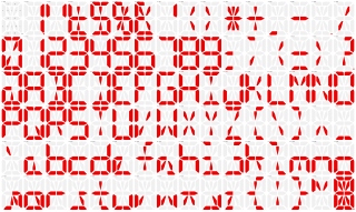
NEW PRODUCTS – Adafruit 14-Segment Alphanumeric LED FeatherWing / Adafruit 0.54″ Quad Alphanumeric FeatherWing Display Combos – White / Blue / Green / Red / Yellow / Yellow-Green.
The schematic shows a BCD to 7 Segment Display for one of the digits of a digital clock. The following components are used.
- CD4511 - BCD to 7 Segment Display Decoder IC
- LSHD-A103 - 7 Segment LED Common Cathode Display
- Here are the 7-segment display markings sorted by sizes, this can often be seen on Ebay photos and reveal if they are specifying a wrong size.
- Real Time Electronic Circuit Simulator.Include PIC, AVR and Arduino simulation.Code Editor & Debugger for Arduino, GcBasic, PIC asm, AVR asm.
- You can also display characters by setting On/Off each display's segment (only available in full version).
7 Segment Display
A 7 Segment LED display generally has 8 input connections, one for each LED segment and one that acts as a common terminal. There are 2 types of 7 Segment LED digital display.
- Common Cathode Display – all the cathode connections of the LEDs are connected to ground. A logic '1' applied to the anode terminal of the individual segment illuminates it.
- Common Anode Display – all the anode connections of the LEDs are connected to VCC. A logic '0' applied to the cathode terminal of the individual segment illuminates it.


BCD to 7 Segment Display Decoder
A BCD to Seven Segment decoder is a combinational logic circuit that accepts a decimal digit in BCD (input) and generates appropriate outputs for the segments to display the input decimal digit.


The truth table is extracted from the CD4511 IC datasheet. This truth table is interactive. Click on any row to see the respective 7 segment display output.
The input bits are D (MSB) to A (LSB) and the outputs are the segments a to g. For input values A to F, the display is blanked (outputs are all 0).
The logic circuit to implement the BCD to 7 Segment Decoder can be designed using the truth table,.
Learn by Doing
Design a BCD to 7 Segment Decoder to deepen your understanding of the circuit.
Segment7 Standard
- Heavy boxes perform quick waltzes and jigs
14 Segment Display Counter
- OpenType
14 Segment Display Driver
